Glass Railing Systems: Choosing Posts, Base Channels and Top Rails
Glass railing enquiries become easier to compare when the connection layout is defined before individual fittings are selected. A post-supported arrangement, a continuous base shoe and a slotted upper rail describe different parts of an assembly. A photograph may show several of them together, but it does not establish which components are included in a quotation. Begin with a marked plan and identify the glass edges, supporting construction and intended rail line. This guide explains what information to prepare for the four product families in this range.
Keep the glass schedule and hardware schedule linked by position. Record the panel dimensions, thickness, joint locations and surrounding finishes, then mark each post, channel or rail section on the same drawing. State the material and appearance requirements separately from geometry. A polished surface does not identify an alloy, and a visually similar fitting may have a different mounting interface. Product selection should be reviewed against the complete project rather than a single isolated image.
Preparing a Glass Railing Enquiry with Hengke Casting
Hengke Casting can review enquiries that distinguish the proposed components and their connection details. Send drawings and quantities for the actual installation, together with any required supporting documents. Identify whether the request concerns uprights, glass attachments, a base profile, an upper rail or a coordinated group of components. Ask for a clear list of included and excluded items. Confirm the proposed version and supply arrangements before placing an order, and keep the approved reference available for later replacements.
Understand the Connection Layout
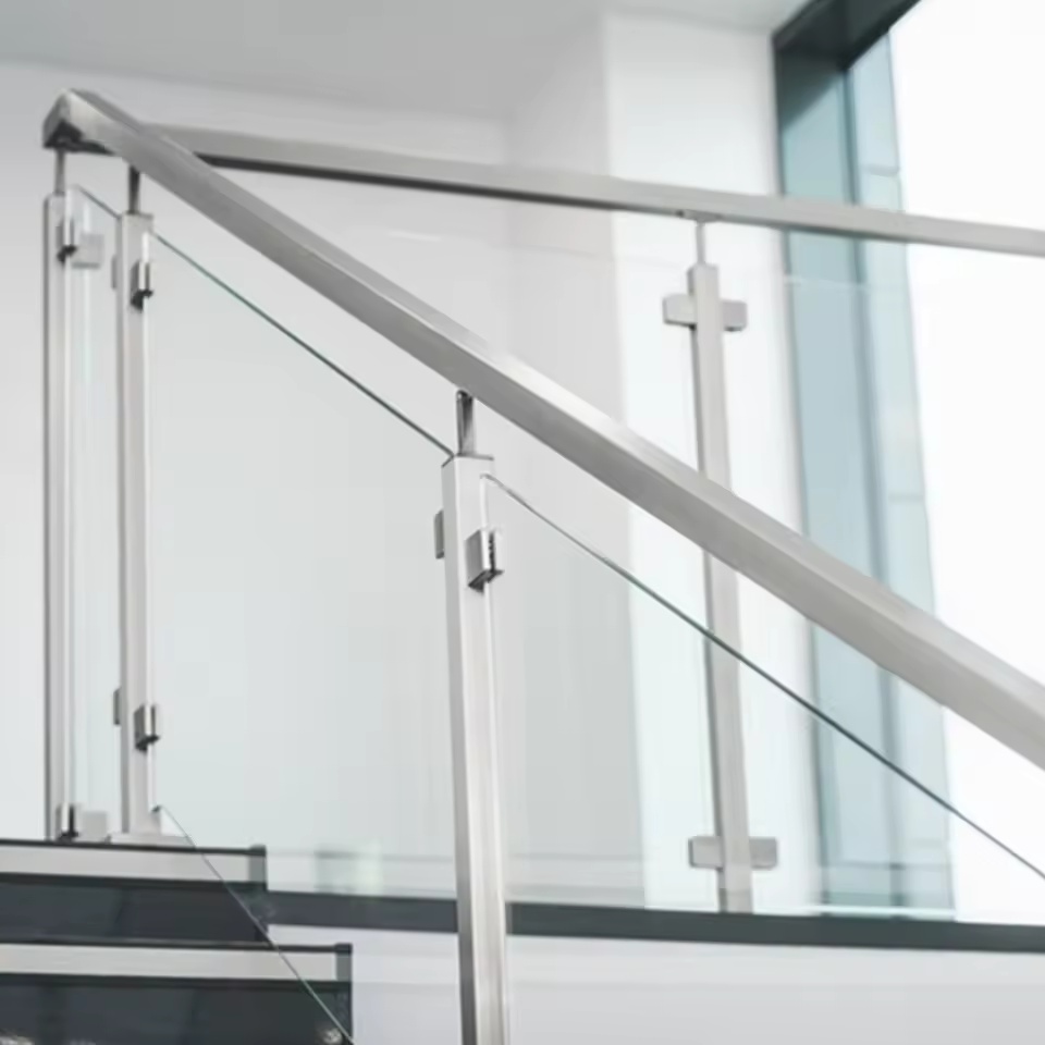
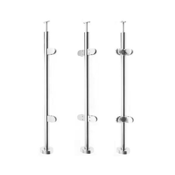
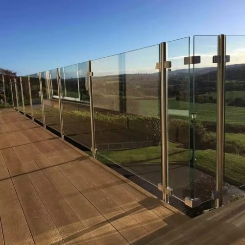
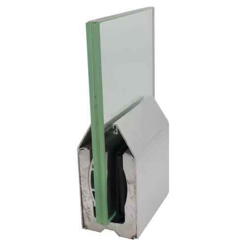
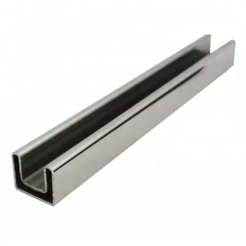
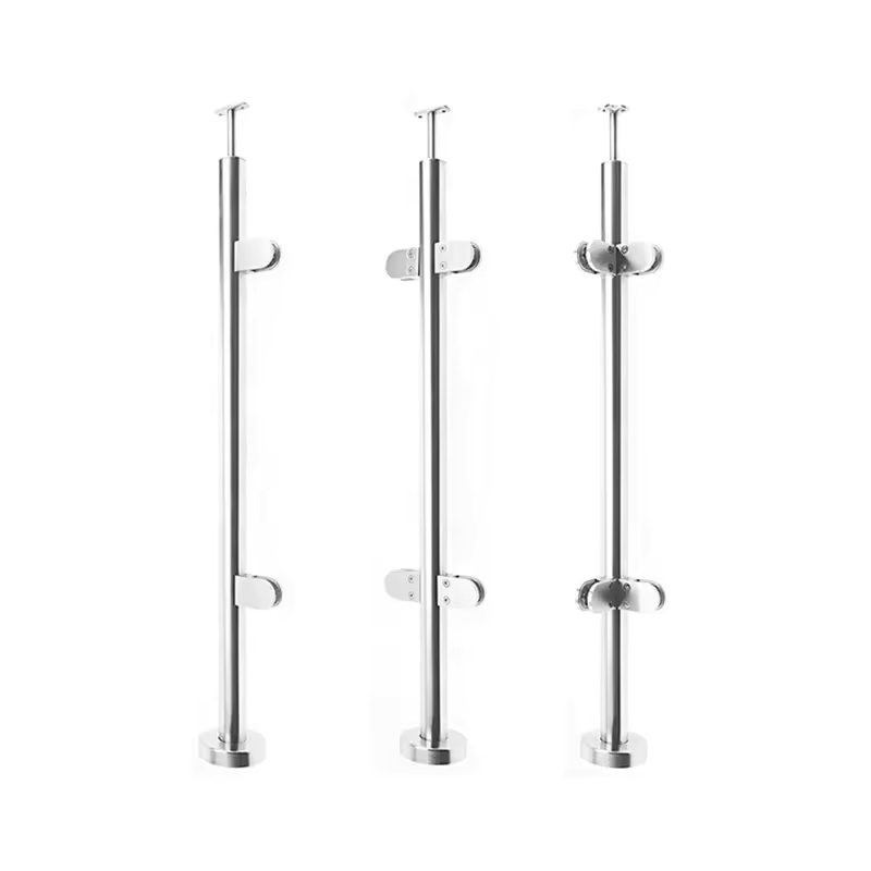
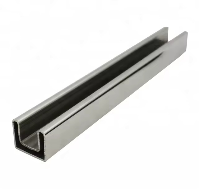
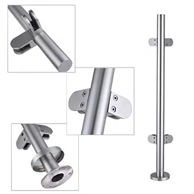
A round or square post system uses upright members and glass attachments as identifiable interfaces. The important questions concern where the uprights are positioned, how they meet the supporting construction and how the glass connections align. Review the connection at the start, middle and corner of a run separately. An installation photograph can illustrate the arrangement, while a dimensioned drawing is needed to identify the proposed components and their actual fit.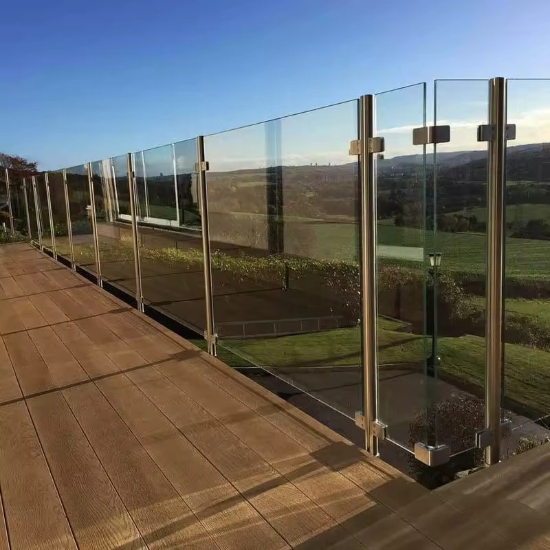 A continuous U-channel base shoe receives the lower glass edge through a compatible insert and clamping arrangement. A slotted top rail sits at the upper glass edge through its matching interface. These are separate functions. A small section of top rail should not be mistaken for a bottom base shoe simply because both have an opening that resembles a channel. Compare the installed position, cross section and fixing arrangement together.
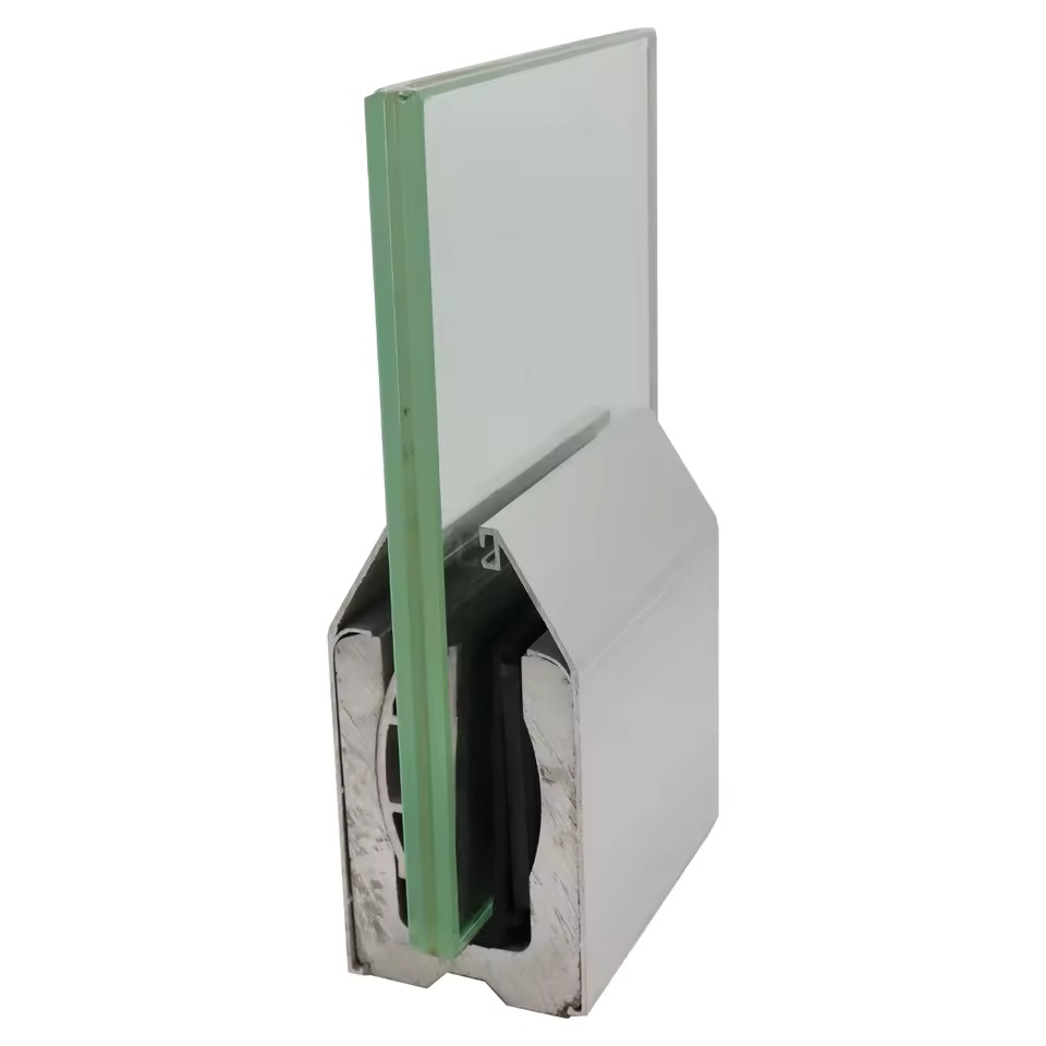 The four families can appear in different overall layouts, but they should not be assumed to form an interchangeable kit. Confirm the selected post, glass attachment, profile, insert and termination as a coordinated specification. If a drawing changes, revisit the affected interfaces before ordering additional parts. Retain the revision date with the hardware schedule so that enquiries, samples and delivered items can be compared against the same reference.
Four Product Families to Compare
The product pages below separate the principal geometries. Use them as starting points for an enquiry, then provide the dimensions and project information needed to select a version. The pictured arrangements illustrate product configuration; they are not presented as completed Hengke Casting projects or evidence of a particular load capacity.
Round posts have a cylindrical upright section, while square posts present a different outside profile. Their glass attachment offsets, base positions and top connections must be checked independently. The base shoe family instead presents a continuous lower-edge interface, and the slotted rail family addresses the top edge. Choose each component for its actual location in the assembly. Do not select a part solely because its surface finish resembles another item already specified.
Build a Dimensioned Component Schedule
A useful schedule follows the installation from one end to the other. Give each run and junction a position reference that appears on the drawings and on the quantity list. Separate repeated positions from exceptional conditions, such as corners or wall terminations. The following steps help keep the enquiry organised without assuming that one standard connection fits every location.
- Plan: Show straight runs, corners, changes in direction and the supporting construction. Mark the intended positions of uprights or continuous profiles. Include dimensions to surrounding walls and finished surfaces so that the hardware is reviewed in context.
- Glass: Record panel dimensions, thickness, joint gaps and the specified edge preparation. Identify any holes or other features shown on the approved glass drawing. Confirm compatibility with the proposed clamp, insert or profile before glass production is arranged.
- Mounting: Describe the supporting construction and provide the relevant connection details. Identify fixing centres, access and clearances. The suitability of substrate fixings and the complete assembly requires project-specific review rather than selection from a product photograph.
- Top edge: Mark the intended handrail or top rail line, its junctions and its ends. Confirm the profile opening, insert and any separate connectors. Show how the rail meets corners and adjacent surfaces without relying on an overall image to communicate dimensions.
- Appearance: State the required material specification and finish reference for each exposed component. Identify colour, texture and visible-face requirements. Ask for confirmation that the selected version can be supplied to the agreed appearance, including any sample approval arrangements.
- Supply: List quantities by position and identify what must be included with each item. Clarify inserts, screws, covers, connectors and separately sourced fixings. Request packaging and identification that allow the delivered components to be matched to the schedule.
Before approving an order, compare the proposed drawings and component list with the latest project revision. Resolve any difference in dimensions, supplied scope or appearance. A clear record of the accepted version is more useful than a general product name when matching future orders. Keep unresolved project requirements visible in the enquiry instead of treating an attractive photograph as sufficient evidence of suitability.
Review Samples and Supporting Documents
When samples are required, identify the connection they are intended to demonstrate. A finish sample can help review appearance, while a component sample can assist with dimensional comparison. Neither should be treated as proof of performance for an entire installation. Agree the relevant checks and documents with the parties responsible for the project. Record the accepted reference and any conditions before the main order is confirmed.
Common Fit Questions to Resolve
Many avoidable discrepancies start with information that was assumed rather than recorded. A generic description such as glass railing does not identify the post section, the position of the glass connection or the type of rail profile. The following three checks help separate appearance, geometry and supplied scope. Address them in the drawings and quotation so that each participant is working from the same specification.1. Posts and Glass AttachmentsFor post-supported layouts, compare the upright section, post height, glass attachment centres and mounting interface. Check whether the pictured attachment belongs to the proposed post version. Review end and corner positions separately from intermediate positions. Where a top connection is required, identify its relationship to the rail profile. Do not assume that different post shapes use the same inserts, clamps or fixing positions simply because their finished appearance is similar.2. Base Shoe and Top Rail ProfilesIdentify where the profile is installed and which glass edge it receives. For a base shoe, show the lower-edge engagement and the connection to the supporting construction. For a slotted top rail, show the upper-edge interface and the rail junctions. Confirm the matching insert and profile dimensions. A section drawing is especially useful when photographs show an isolated length of metal without a clear installed orientation.3. Finish and Included ComponentsSeparate finish requirements from the component list. A photograph of an assembled railing may include glass, posts, rails, covers and fixings, while a quotation may cover only selected metal components. Ask for an explicit scope and an agreed appearance reference. Confirm whether inserts and screws are supplied with the selected part and identify items to be sourced separately. Keep the specification tied to the quoted version rather than an unqualified catalogue image.
Information for Different Layout Positions
An overall run contains several connection conditions. Even where the same finish is used throughout, starts, corners, stairs and terminations may require different dimensional reviews. Mark these locations on the plan and provide the corresponding elevations or sections. The examples below describe information to include, rather than claims that every pictured component is suitable for each application.
Straight Glass Runs
For a straight run, show its overall length, panel divisions and the positions of posts or profiles. Identify the joint gaps and the proposed top edge. Check how the first and last panels are retained, and record dimensions to adjoining surfaces. Repeated positions can share a reference only when their dimensions and connection requirements are actually the same.
Stair and Ramp Positions
Where a layout follows a slope, provide the relevant angle and elevation. Show the relationship between the glass panels, supports and rail line. Check the proposed attachment and rail junction against that geometry rather than assuming a level-run component can be reused. Identify any special edge or connection details required by the project for review before ordering.
Corners and Direction Changes
At a corner, state the actual angle and show the meeting glass edges and rail sections. Include clearances and the position of the supporting construction. A nominal right-angle description does not communicate every offset or joint dimension. Mark any connector or termination separately so that the component list follows the drawing.
Wall and End Conditions
For a wall or end condition, show the available space and the intended fixing interface. Identify how the glass or upper rail terminates and whether a separate connector or cover is required. Include access for assembly and the relationship to adjacent finishes. Confirm the selected end component rather than leaving the quotation to infer it from a distant installation image.
Packaging and Delivery Groups
For larger enquiries, group items by the marked positions or installation areas. Request identification that connects a package to the accepted component schedule. Confirm the quantities of small parts such as inserts, screws and covers, and agree which items are supplied separately. Delivery grouping is an order requirement to discuss, not an assumed feature of every product.
Keep the Approved Specification Current
Changes to panel divisions, support positions or finish levels can affect several interfaces at once. Update the drawings and component schedule together, then ask for confirmation of the affected versions. Keep samples, quotations and delivery records tied to the same revision. This helps distinguish a replacement for an approved item from a new enquiry with different dimensions. Review the complete project requirements before the final assembly is selected.
 To discuss a new enquiry, send Hengke Casting the layout, selected product family, quantities and material or finish requirements. Include any documents needed for review and a clear delivery destination. Ask the quotation to identify the proposed component version and supplied scope. Confirm sample arrangements, packaging and delivery terms for that specific request.
 The Glass Railing Systems category links the round post, square post, U-channel base shoe and slotted top rail pages. Compare the relevant connection details there and use a dimensioned drawing to identify the required version. Product photographs help communicate shape and appearance; the project specification remains the reference for final selection.