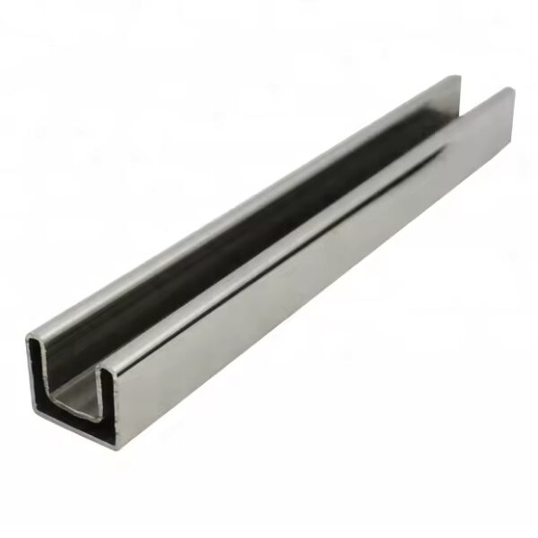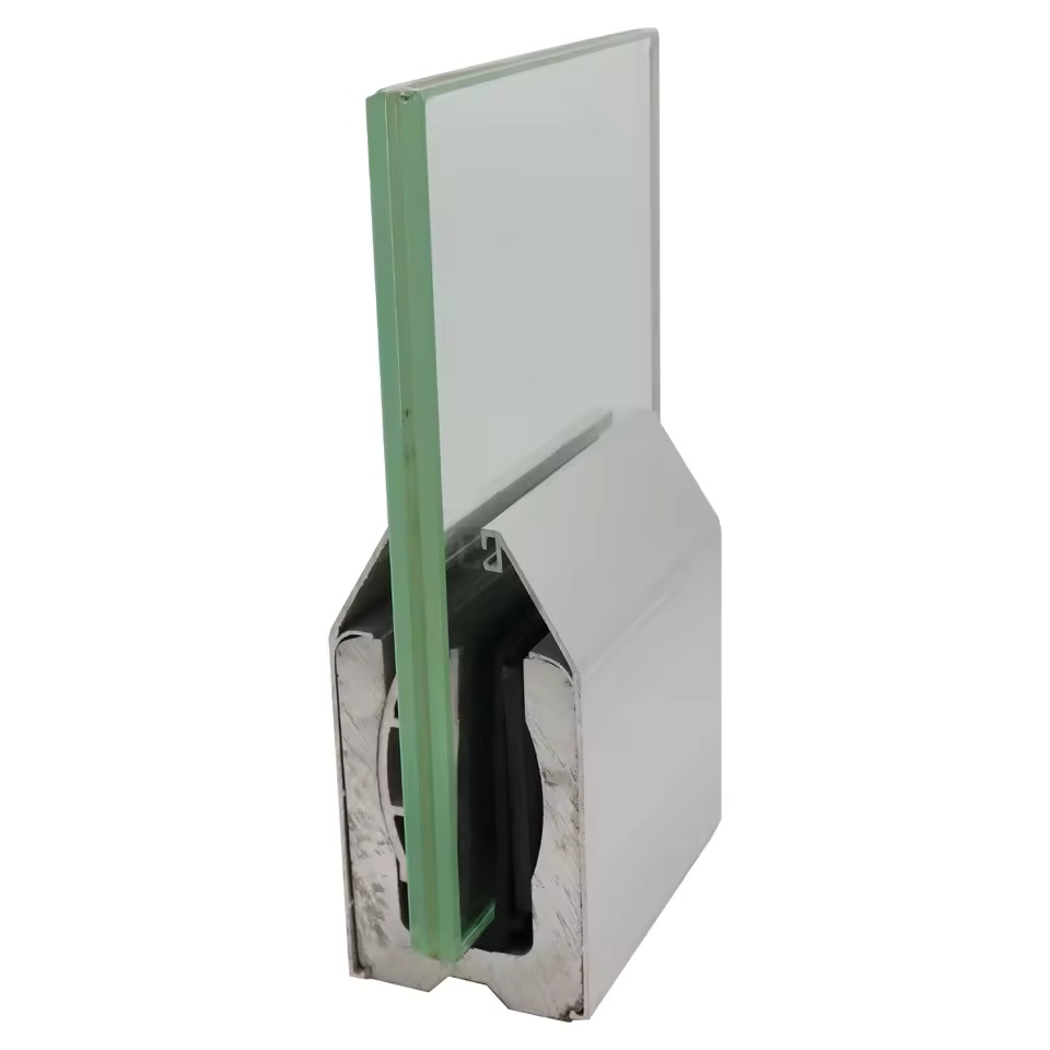
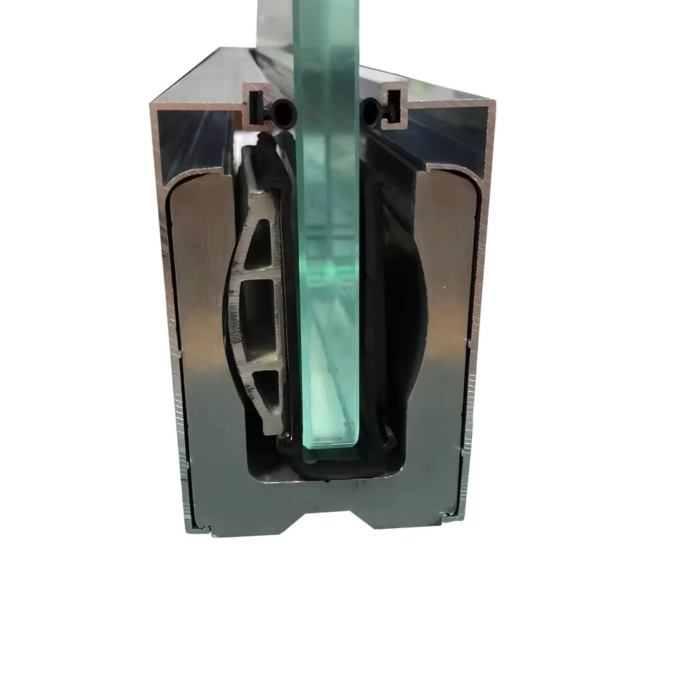


Aluminum U Channel Glass Railing Systems are selected for glass layouts with a continuous supporting base channel. A continuous U-shaped base shoe receives the lower glass edge through a compatible insert and clamping arrangement. Confirm the geometry against the complete layout before choosing components.
Hengke Casting can review required certification documentation for the specified components. Confirm the applicable requirements and supporting records before ordering.
| System layout Aluminum U Channel Glass Railing Systems
| A continuous U-shaped base shoe receives the lower glass edge through a compatible insert and clamping arrangement. Lower glass edge seated within the base shoe U-shaped base profile with project-specific fixing to the supporting construction Confirm the top edge and end termination. Specify the required appearance. |
| Connection review | Check base profile, glass insertion depth, fixing centres and finished floor clearances. Match glass thickness and insert dimensions. Identify the supporting construction. Confirm the complete component list. |
| Project dimensions | Panel lengths and heights Post or profile positions Junction angles Glass edge clearances Mounting hole positions Finish levels and offsets Access for fitting and maintenance |
| Finish specification | State the required surface appearance. Provide a colour or finish reference. Identify all exposed faces. Confirm available options for the selected components. Keep the approved finish recorded for repeat orders. |
| Product geometry | A continuous U-shaped base shoe receives the lower glass edge through a compatible insert and clamping arrangement. |
| Dimensions to confirm | Connection details: Lower glass edge seated within the base shoe. |
| Mounting details: U-shaped base profile with project-specific fixing to the supporting construction. | |
| Critical dimensions: base profile, glass insertion depth, fixing centres and finished floor clearances. | |
| Glass data: thickness, panel size, edge preparation and insert compatibility. | |
| Material review | State the required alloy for each metal component. Request confirmation against the selected drawing. |
| Identify material documentation required for the project. Confirm the insert and fixing materials separately. | |
| Appearance alone does not establish alloy grade. | |
| Layout information | Straight-run dimensions Stair or ramp positions where applicable Corners and changes in direction Start and end conditions Wall connections if required Supporting slab or other substrate Top rail continuity and joints Access around the installation Delivery grouping by marked position |
| Drawings | Supply a dimensioned plan, elevations and connection details for the actual installation. |
| Project requirements | Identify the applicable project requirements and the documents needed before selecting the complete assembly. |
| Review checklist | Selected component version Dimensions and interfaces Material specification Surface finish reference Included and separately sourced components Project-specific suitability review Agreed supply and delivery scope |



Specify this arrangement from a dimensioned layout showing the glass, supporting construction and adjacent junctions. Record base profile, glass insertion depth, fixing centres and finished floor clearances, together with the glass thickness and edge preparation. Confirm how the selected component interfaces with neighbouring parts.
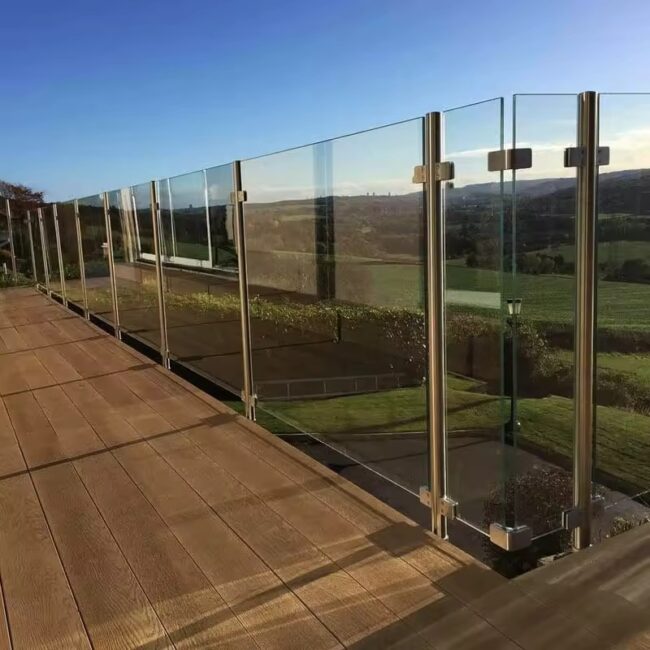
Hengke Casting can review an enquiry that identifies the required material, appearance and supplied component list. Ask for confirmation of the proposed version and any documentation needed for the project. Installation examples illustrate a layout and are not presented as completed Hengke Casting projects or evidence of a rated capacity.
Compare the related layouts below, or return to Glass Railing Systems to review the other connection types. Project-specific suitability and assembly details must be confirmed before ordering.